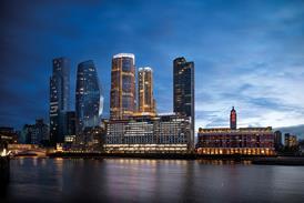
Woolgate Exchange is a massive speculative office on a restricted site between Basinghall Street and Coleman Street, close to Moorgate Station. The building, which is nearly built, has 32 000 m2 of office accommodation arranged on basement, ground and eight upper floors. It is spacious enough for three major dealing floors. The entire development has been pre-let to Westdeutsche Landesbank Girozentrale.
To meet the requirements of the developer and planning authorities, the facade needed skilful architectural treatment. The site bordered two conservation areas and the envelope had to meet the client's requirements for a minimum wall thickness and glazing that allowed maximum daylight to flood the interior. Architect Sidell Gibson's scheme was granted planning permission in November 1997.
To keep the planners happy, the facades facing the street are clad in Portland stone to match traditional buildings nearby. The elevations hidden from the street were dealt with more simply. The north facade is constructed from London Stock Brick and the south is a sloping curtain wall, concentrating value on the public facades. "We invest money only where it creates value," says Scrivener.
The challenge for the design team was to keep the wall's thickness to a minimum on the two traditional-looking elevations while creating enough relief and depth in the stonework to give the appearance of a quality building at the cost of a standard office. The facade's design was to "follow all the basic commercial rules", Scrivener explains.
The task of constructing the ÂŁ69m office was just as onerous. The scheme was negotiated as a design-and-build with a guaranteed maximum price. Balfour Beatty was awarded the contract in March 1998 and the design team was novated to the contractor early on. "We employed the contractor to manage the design team from an early stage to produce a realistic price," says Scrivener. "The price MEPC agreed in October 1998 will be the price it will pay in July 2000. It takes away a lot of the debate."
Now, just a month from completion, the final touches are being added to the facade. Slender Portland stone columns stretch from a pavement colonnade to the seventh floor parapet, broken by fluted capitals at the second, fifth and seventh floors. Between the columns, large rectangular windows arranged on a regular grid peep out from deep recesses. The traditional appearance of the building's east and west elevations belies the sophisticated method of its construction.
"The depth on the walls is 435 mm," says Scrivener, "which is 50 to 75 mm thinner than you could reasonably expect when achieving reveals in the stone facades up to 220 mm deep. This makes the stone look much more solid than it is." To achieve this significant reduction in width, the designers turned to structural engineer Waterman Partnership.
Steel frame cast into concrete sections
Waterman devised a system of construction that combined the structural properties of steel and concrete into one unit to reduce wall thickness. The external steel columns were pre-encased in concrete and delivered to site in sections up to two storeys high. The outer face of the concrete was moulded to mimic the profile of the Portland stone cladding and fixings were incorporated to allow the cladding to be fitted easily.
Once the structural steel frame started to rise from the basement, precast concrete spandrel panels were installed between the columns to form a facade of concrete frames into which the windows are installed. Once fitted, the windows ensure that the facade is weatherproof and work can proceed unhindered inside the building.
This method had the advantage of taking the labour-intensive installation of the Portland stone off the critical construction programme. "Once the precast concrete panels were up, the remainder of the cladding installation was off the critical path," says Mark Boyland, a partner in architect Sidell Gibson.
The Portland stone skin is constructed from a series of 75 mm thick ashlar blocks that are attached to the concrete wall sections using bespoke bracketing. To save time and keep costs to a minimum, most of the detailing in the stonework is created by machine. "If this building had been constructed 100 years ago, all the detailing would have been done by hand," Boyland explains. The team spent a lot of time in Portland, Dorset, selecting suitable stone for the facade. Boyland says: "By sitting down with the stonemasons and talking it through, we were able to design the stonework so that all the details could be created by machine."
When it came to the design for the windows, attention to detail was critical to bring the scheme in on budget and to keep the wall thickness to a minimum. The architect chose to use SchĂźco's standard window sections throughout. The window units span up to 4 m between the main vertical structural steelwork and reach almost 2800 mm high to meet the client's requirement for full-height glazing.
However, with such large spans on conventional windows, wind loading becomes a problem. The usual solution would be to deepen the window mullions to add strength to the frame. But this would also thicken the width of the wall, taking up valuable office space and blocking out daylight. To keep costs down, the contractor also wanted to use a standard window system.
Balfour Beatty employed window and cladding technology consultant Wintech to resolve the conundrum.
"We decided to enhance the window's performance by adding the structure to the outside of the window," explains Chris Macey, group managing director of Wintech.
Macey added a slender aluminium column to each of the curtain wall's two central mullions. The columns, or "wind posts", as they have come to be known, are attached to the mullion by three brackets spaced evenly over the window's height. "This had the advantage of adding strength without damaging the waterproofing," says Macey. "It also means that the window frames can be much smaller and lighter."
To incorporate this additional support unobtrusively into the facade design, the architect has designed scaled-down versions of the fluted capitals that surmount the main structural columns for the wind posts. A moving joint at the top of the column stops any of the wind load being transferred through the decorative elements on the sill and lintel. The wind load is transferred through secondary steelwork back to the main supporting steelwork.
The design for the cladding began a year before the appointment of the cladding contractor. The project looks set to meet the 21 July deadline. Five floors have already been handed over to the fit-out contractor, Interior. Following the team's success at Woolgate, the developer is set to take the same group to its next London project, just down the road in Lombard Street.
Credits
client MEPC architect Sidell Gibson design-and-build contractor Balfour Beatty structural engineer Waterman Partnership services engineer Hilson Moran Partnership cladding consultant Wintech quantity surveyor Davis Langdon & Everest
Cladding
- 1
- 2
- 3Currently reading
Think thin


