An M&E contractor on a south London civic centre project has come up with a neat way of packaging all the services together at floor level. Stephen Kennett gets down to the detail
The current economic climate has not dented clientsŌĆÖ enthusiasm to get projects completed as quickly as possible and at minimum risk. The development of the civic centre in Woolwich for the London Borough of Greenwich is a case in point. A key part of the strategy for streamlining the buildingŌĆÖs delivery has been to maximise the use of off-site fabrication of M&E services.
Prefabricated plant rooms and service risers are not new, but SES - the M&E contractor on the project - has devised a lightweight modular system that packages together the raised access floor and the distribution of the building services on each floor level. It takes an eight-man team just four weeks to kit out each 3,000m2 floor - a quarter of the workforce it would traditionally take.
ItŌĆÖs an unusual approach, given that in most offices the vast majority of the services are distributed in the void above the suspended ceiling. But this isnŌĆÖt a conventional air-conditioned office. Rather than using four-pipe fan coils to deliver cooled air at high level, it uses a combination of chilled beams and exposed concrete ceiling soffits, together with displacement ventilation that sends fresh air through grilles in the floor. Together, these measures help harness the buildingŌĆÖs thermal mass and cut energy consumption.
Using this approach, services traditionally located above the ceiling can be concealed in the space beneath the floor - space normally reserved for power and data cabling. The idea is that the ventilation ductwork will deliver air into the floor plenum while the chilled water and heating pipework, power for the light fittings and fire detection containment drop down through holes to the floor below.
For this approach to work the structural engineers have also had to break with convention. The building uses a steel structural frame with precast concrete planks to create the floors. These provide the contoured exposed concrete ceiling finish but, says Jeremy Wedge, associate with structural engineer Buro Happold, rather than sitting on the steel beams they hang from the bottom flange of the 850mm deep I-beams.
Additional stiffening was added to the beams to make this possible, but the main outcome is that the beams protrude well above concrete floor level, creating a zone that is suitable for the raised access floor and services.
Azim Jasat, director of SES Prism - the contractorŌĆÖs prefabrication arm - says off-site manufacture was embedded in the design from day one and the programme has progressed quickly. When it came to floor modules, SES saw an opportunity to take prefabrication a step further - though Jasat admits it has meant a lot more investment and work at the design development stage.
One of the biggest challenges was creating the frame for the floor module. Prototypes were made at the contractorŌĆÖs Yorkshire factory to find the best compromise between strength and cost. The first version used very lightweight steel channel sections, which worked when static but buckled as soon as it was lifted for transporting, says Jasat.
Two further versions were developed to improve the design. The final modules are about 600mm deep, in a variety of formats. The simplest contain baskets for cabling; others include ventilation ductwork, chilled water and heating pipework and controls.
A key feature of the frame is the integration of adjustable pedestal feet into the top and bottom of the uprights. These can be adjusted to level the frame and fine-tune the height of the floor tiles.
Beneath the floor
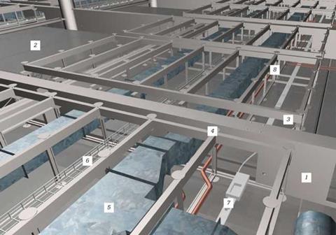
The design of the M&E and floor modules was modelled in 3D; all the quantities were taken directly from this model and used in the manufacturing process to cut down on time and waste.
- Steel I-beams supporting floor
- Precast concrete floor planks
- Prefabricated module frame
- Adjustable pedestal feet
- Ventilation ductwork
- Cable tray
- Busbar
- Hot and cold water pipework
║├╔½Ž╚╔·TV in enough adjustability to soak up an uneven floor screed required careful judgement. The more adjustment the module allows for, the shallower the frame has to be - meaning less space for ventilation ducts and pipework. And because there is only millimetres of clearance where the ductwork passes through the voids in the structural steel beams, co-ordination between the M&E and structural design teams was paramount.
More than 900 floor modules are being used on the scheme and about 50 roll out of the factory each week. ŌĆ£With normal manufacturing you try and standardise the product so youŌĆÖre producing the same thing over and over again. What weŌĆÖve done here is come up with an off-site solution for this project, rather than taking an existing product and changing it to suit,ŌĆØ says Jasat.
The modules are delivered to site, where they are craned in at one end of the building and distributed to their position on the floor using a special rig running on tracks. The modules are then lined up and a two-man team makes the pipework, busbar and ductwork connections. They are followed by the flooring contractor who lays the floor tiles before SES carries out the electrical wiring and floor boxes and finally does a quality control check.
Jasat says itŌĆÖs difficult to show that the prefabricated approach is more cost-effective than a traditional solution but there are significant benefits. It removes a large element of the projectŌĆÖs risk, offers improved quality and safety and reduces labour costs. Only eight workers have been needed to fit out the floors for the 18,000m2 building compared with 32 using a traditional system.
The M&E installation package should be complete by the end of the year. Jasat says the approach has generated a lot of interest. All he needs now are the orders to follow.










No comments yet