Finding somewhere to lay the foundations for an office block above LondonŌĆÖs Cannon Street station proved so difficult, the engineers had to call on the structural principles of the Forth Bridge to get the job done
You would think that designing an eight-storey office block was well within the boundaries of conventional engineering. Even when that building is on the edge of the City and has to be squeezed in below the protected views of St PaulŌĆÖs cathedral, it shouldnŌĆÖt be too difficult. But when itŌĆÖs perched directly above a mainline railway station as well as a Tube line and half the site footprint is classed as a scheduled ancient monument, the task suddenly becomes a lot more tricky. For a start, where are you going to locate the foundations, what sort of structure is needed to keep it levitating above a station, and how are you going to build it while 32,000 passengers a day are swarming below?
These problems have all been faced at Cannon Place, but itŌĆÖs only now that a critical stage in the construction is approaching when the success of the innovative design will be put to the test.
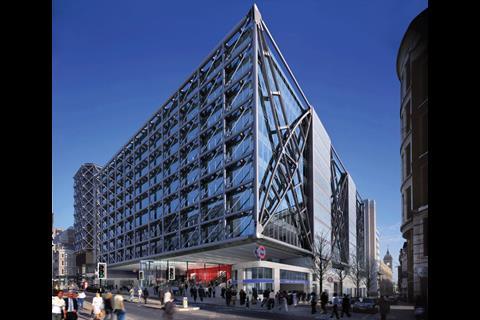
The building supplants a 15-storey sixties office tower and occupies the air rights of the northern third of Cannon Street station. ItŌĆÖs the second scheme that Foggo Associates - the architect, structural and M&E engineer on the project - has designed for the site. The 1997 version was relatively conventional and included two financial trading floors and six further office floors.
But in 2002, developer Hines acquired the leasehold on the site and decided to see if it could make it more appealing. ŌĆ£We went back to the drawing board as it was felt that a more flexible design was needed that would appeal to a range of different tenants,ŌĆØ says project architect David Warrender.
What they came back with was a simple rectangular footprint which virtually fills the entire site, but is split into three 21m wide strips of office space separated by two 12m wide zones which, as well as linking the spaces, accommodate four service cores and two generously sized atriums. As Warrender explains, the plan offers large, uncluttered floors with potential for subdivision.
However, achieving the 21m clear spans for each office zone requires columns at 6m centres along each edge. If these columns were taken down to ground level most would land in an area off limits to large structures.
The constraints on possible solutions were numerous. Cannon Street underground station and the District and Circle line tunnels ruled out putting any significant structure on much of the northern end of the site. It was this limitation which dictated the position of the existing sixties slab block. Immediately to the south of this and below the railway platforms is a service road which again meant that no significant structure could be founded here and on the southern half of the site lie the Cannon Street mainline station platforms and track beds. There was no way these could be altered to accommodate any new structure.
The upshot of all this was that there were only a few areas where any new structure could penetrate down through the station. And there was the scheduled ancient monument status of the site to the south which, while it did not preclude the location of foundations, involved a complex
process of consents to get permission. ŌĆ£In any event the number of penetrations through the archaeology have to be kept to a minimum,ŌĆØ says Warrender.
ŌĆ£The solution is a bit chicken and egg. The plan leads to the structure, but without the structure the plan wouldnŌĆÖt workŌĆØ
David Warrender, Foggo Architects
The solution has been to adopt a technique usually used for building bridges. The idea is to suspend the northern strip of office space above the underground tunnels and to balance this by doing the same on the southern side. The solution is a bit chicken and egg, says Warrender: ŌĆ£The plan leads to the structure, but without the structure the plan wouldnŌĆÖt work.ŌĆØ
Substantial foundations are, of course, still required for the central section of the building where the four cores are located. Space had to be made to take these down through the station concourse and railway arches to the ground beneath.
Jim Fraser, structural engineer on the project, says that because there is very limited headroom below the railway arches, the initial idea was to create hand-dug caissons to create the piles to support the columns. This would have involved sinking a ring of mini-piles and then digging the clay out from the centre by hand and filling it with concrete. However, this was considered too dangerous. ŌĆ£It then became blindingly obvious, why donŌĆÖt you leave the clay in the middle and effectively put a cap on top and create the pile that way,ŌĆØ explains Fraser. The ring of piles is around 3m in diameter and goes down 32m. The main advantage of this solution is that the size of the piling rig needed is much smaller and could operate in the restricted spaces.
Elsewhere, the piles that supported the demolished sixties tower block are also being reused. These piles are underreamed and splay out at the base with square footings. According to Fraser they have high load carrying capacity, but associated with that is a lot of settlement. ŌĆ£We realised it would be difficult, particularly on the edges, to put in other foundations so we decided to adopt them and try as best as possible only to put back as much load as we were taking off because we didnŌĆÖt want anything like those settlements,ŌĆØ he says.
In the middle the loads from the new building match the loads of the old structure reasonably well. However, the cantilevers along the facade are founded on four large ŌĆ£hour-glassŌĆØ structures. Although the piles here could carry greater loads than they were, settlement would become a problem. The answer has been to reinforce them by carefully threading new ones between them. ŌĆ£The settlement should just be the reverse of the heave, which is about 15mm,ŌĆØ says Fraser.
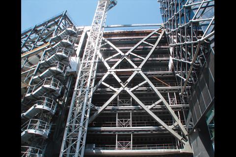
The structure for the central section of the building is now complete and work building the two cantilevered floors is under way. The biggest challenge here is that the cantilevers only work and balance one another when the deep truss structures on all the facades are in place and connected together. Temporary works have been installed to support the bottom floors on each side as they are built, but these arenŌĆÖt strong enough to support all eight floors before the final bracing is installed. The solution has been to install strand jacks at the top of the completed central section, which increase the tension in steel cables attached to the outer edges of the two lowest floors. As the steelwork structure for the subsequent floors is added these cables will hold everything in position. By August the structure will have reached the top, at which point the strand jacks will be released. Only then can the floor decks be concreted. ŌĆ£This will be the moment of truth,ŌĆØ says Fraser.
If all goes to plan the next stage will be to crack on with installing the facade and racing onwards with the fit-out for the summer 2011 completion date.
║├╔½Ž╚╔·TV over a railway station
║├╔½Ž╚╔·TV over a busy railway station comes with its own unique set of problems. The main issue has been trying to keep the station and facilities open while 32,000 passengers a day pass through it, says Alister Offiler, deputy project director with Laing OŌĆÖRourke. ŌĆ£One of the complications was that Network Rail didnŌĆÖt want us to lift anything that could potentially fall from a tower crane.ŌĆØ
The existing roof structure above the station comprises lightweight 150mm thick concrete slabs sitting on box girders and it is not capable of supporting a large load. Although the tower crane bases were overdesigned by 50% and the cranes restricted to lifting no more than a quarter of their capacity, Laing OŌĆÖRourke had to outline to Network Rail how it could erect the building while minimising the risk of anything crashing through the roof.
What it came up with was SLOP - a steelwork lifting operation plan. ŌĆ£We split the structure down into two-storey sections and analysed the 150mm thick slab so that if you dropped, say, a column section from 8m or two storeys, it wouldnŌĆÖt penetrate the slab,ŌĆØ explains Offiler. There was still a risk of things falling off the edge of the structure as the building went up, so 300mm thick glulam sheets were laid on the areas of the station roof in danger. ŌĆ£If anything fell from level eight this timber would catch itŌĆ” and absorb the impact,ŌĆØ says Offiler.
The plan was to build the central section of the building first, followed by the two cantilevered spaces. While the existing tower block was being demolished down to the roof level, areas inside the station were hoarded off where the cores would go down. This enabled the voids to be created for the new structure to come up through while at the same time work to install the new foundations was under way.
As the steelwork for the cores was going up, the support columns and beams for the bottom level of the building were threaded beneath the existing station roof and the concrete slab poured. Only then could the old roof be removed and work on the structure continue.
All in the balance
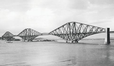
The key to the structural design on Cannon Place is the idea of cantilevering the northern and southern strips of office space and using them to balance one another so that they do not require supports being sunk down through the mainline station. ItŌĆÖs an idea inspired by the structural principles of the Forth Bridge (pictured below), but the upshot is that it requires the transfer of huge loads.
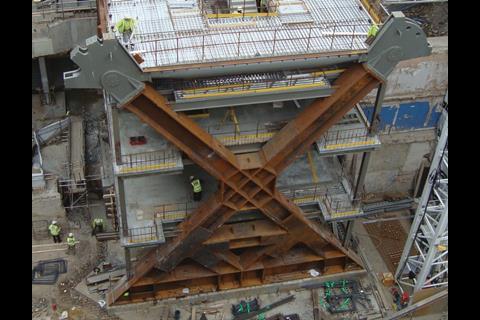
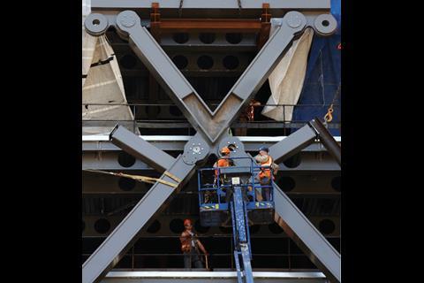
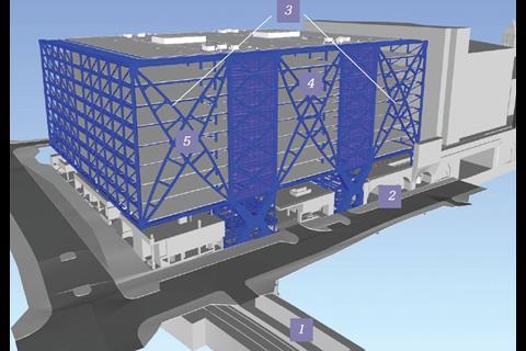
To make this possible trussed elements are being created on all four sides of the building. On the north and south the facades span 67.5m by the addition of tensile braces which run diagonally between the 6m bays on each level. These pick up the loads from the end of the 21m span beams on each floor and in turn transfer it to the eight-storey X-shaped trusses that dominate the buildingŌĆÖs east and west facades (see diagram below).
The loads are then transferred to the ground through sculptural concrete and steel footings - so-called ŌĆ£hour glassŌĆØ structures.
The central band of office space and the internal cores, on the other hand, are founded more traditionally by finding positions on the railway concourse through which the structure could pass.
Downloads
Diagram
Other, Size 0.1 mb










No comments yet