


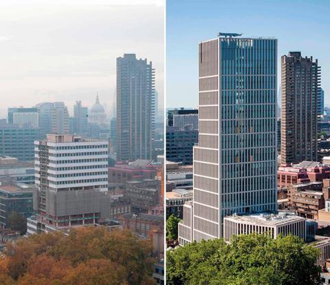
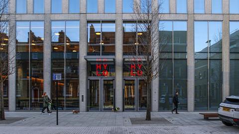
The team behind the Hylo building in Londonﻗs Bunhill Row were so impressed by Richard Siefertﻗs original Finsbury Tower, they decided to extend it by 13 storeys rather than replace it ﻗ saving 35% of the carbon footprint of a new-build
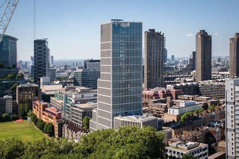
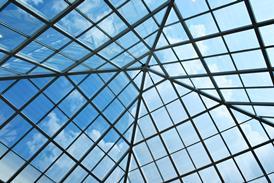
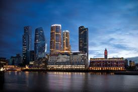
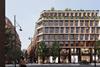
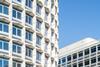
Two unusual features distinguish the new, ﺡ۲130m Hylo building on Londonﻗs Bunhill Row from others of its ilk. Brick clad, it breaks with the high-rise office tradition of an allﻗglass facade. This softens its appearance and helps it to blend in with neighbouring residential towers, which include the Barbican. The second feature is less overt but more significant: rather than demolishing the 16-storey incumbent tower, the new scheme extends it upwards by 70% and sideways by another 24%, which more than doubles the net lettable space while saving 35% of the carbon footprint of a new-build scheme.
Vertically extending the existing Finsbury Tower, which was completed in 1967, has precedent. The team behind this project ﻗ developer CIT, structural engineer AKTII and contractor Mace ﻗ collaborated on an earlier project called Southbank Tower, which coincidentally was designed by the same architect, Richard Siefert.
There are some important differences, however. Southbank Tower was a residential scheme with a correspondingly smaller footprint and the extension was less, adding 11 storeys to the 30-storey tower. Hylo was more ambitious because the tower footprint is bigger and the extension is higher, which in turn demanded a greater degree of intervention to provide the standards of vertical transportation expected of a modern high-rise office building.
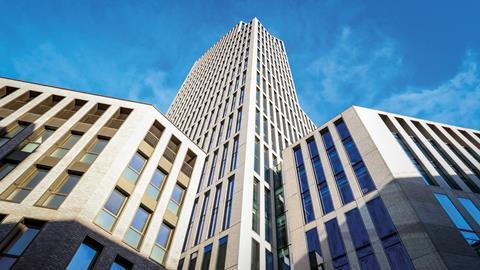
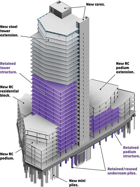
Finsbury Tower also featured a podium with four-storey blocks to the north and south of the tower. These have also been extruded upwards to seven storeys.
Finsbury Tower featured a single core offset to the north-east side of the tower. As this was far too small to provide enough lift shafts to service the extra space, two new cores have been built on the northern corners of the tower to house high-speed, double-deck lifts. These extend partially outside the existing tower footprint to the north to increase the amount of space. Because the new cores overlap with the existing core, it had to be demolished.
The first step was to see if extending the existing building was a viable option. Albert Williamson-Taylor, AKTII design director, explains the process: ﻗWe did a historical check, including when it was built and to which codes. This gives you a very good idea of what kind of substructure it has got, as we have a lot of knowledge of London buildings. This enabled us to make a very early assessment.ﻗ
This concluded that the building featured a concrete frame supported by under-reamed piles which could support the extra floors subject to some minor modifications.
We did a historical check, including when it was built and to which codes. This gives you a very good idea of what kind of substructure it has got
Albert Williamson-Taylor, design director, AKTII
The next step was to carry out detailed investigation and analysis, including sourcing the original drawings from Pell Frischmann, which was the structural engineer for Finsbury Tower. Williamson-Taylor says that these investigations usually reveal that more floors can be added than the original assessment rather than fewer.
The combination of new lightweight and composite materials combined with advances in computer analysis mean existing structures can have even more floors added to them than was previously understood.
For example, measured by building height, Finsbury Tower has been extended by 70%, whereas Southbank Tower was extended by 40%. Williamson-Taylor says Southbank Tower was one of the first projects where AKTII used CFD (computational fluid dynamics) analysis to understand wind loadings on the structure.
ﻗThis is so much more developed and sophisticated now,ﻗ Williamson-Taylor explains. ﻗWe can analyse the wind loadings, the stresses and load paths through the structure and material capabilities.
ﻗNow we know exactly how the building is behaving horizontally, vertically and in combination.ﻗ
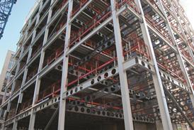
The substructure and superstructure was capable of supporting a steel frame with composite floors with some localised column strengthening. The same solution was used at Southbank Tower albeit without the column strengthening.
Weight has been minimised where possible; the roof is a lightweight concrete structure, and an unusual approach was adopted for the cladding system to keep the weight down.
Demolishing the old core and constructing two new ones has made this job considerably more complex than Southbank Tower. Demolishing the core also meant the existing 16 floors lost their structural stability system, which called for temporary bracing. Diagonal bracing was erected between the existing slabs.
David Bee, a director at contractor Mace, who was involved throughout the project, describes the core demolition as ﻗa bit nervyﻗ since without the support of the core the remaining building wanted to lean over with the only restraint provided by the temporary works. ﻗThere was a lot of ongoing monitoring, with some quite stringent trigger levels,ﻗ Bee says. ﻗHats off to AKTII because it stayed within the tolerances we were working to.ﻗ
Additional piling that was needed for the new cores was threaded between the existing, under-reamed piles. ﻗThat made the new foundations complex because we couldnﻗt demolish the under-reamed piles,ﻗ Bee says.
ﻗThe foundations for the new cores is a hybrid of existing and new piles which creates some settlement issues because the existing piles arenﻗt going anywhere but the new piles will move to some extent.ﻗ
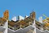
Bee says the settlement issue meant that the cores had to be built deliberately out of plumb on the grounds these would move into the correct position once the new piles settled. The new cores are slipformed.
Bee explains that the concrete specialist, J Coffey, had to make slight corrections to the slipform as it went up to ensure that the core was in the right place. Bee warns that a minor discrepancy at the base of the core has a big impact at the top. ﻗAt ground level we are talking a few millimetres but, when you extend the core up 30 floors, a few millimetres at the bottom can mean 30mm to 40mm at the top.ﻗ
A new concrete frame was built between the new cores and in front of these to connect to the existing floor slabs. Bee says this part of the job was made more challenging because a section of the existing floor slab had to be broken out to expose enough old reinforcement so this could overlap with that of the new slab. It proved difficult to avoid damaging the existing reinforcement in some areas, so steel couplers were used instead.
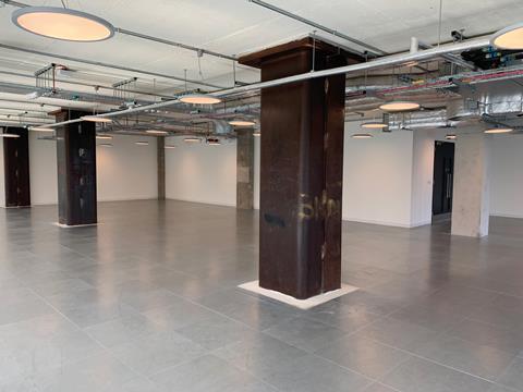
Some of the existing columns were strengthened by encasing these with steel jackets. Bee says the steel was 30mm thick lower down the building where the loads were greatest. Getting the steel sections into position was challenging, as once the jackets were lifted onto the edge of the floorplate by the crane these had to be moved across the floorplate using a G20 pick and carry crane with a magnet lifter. These were installed using a block and tackle system.
>>> Also read: Cost model: Impact of building regulation changes
>>> Also read: The Forge: a platform for transforming office construction
The existing tower floorplates were extended on the west, south and east sides because this created more lettable space and because the tower was set back from the podium level on the east side. The floors were extended by 300mm, with some of the lower floors extended by 800mm using 10mm-12mm thick plates.
Each plate overlapped the existing structure by 1m. These were bolted to the slab from above with a section perpendicular to the main plate fixed to the edge of the slab.
The relative positions of the existing floors and the new core did not quite work out as predicted. ﻗThe existing structure had leaned towards the cores and the prediction was that it would be pushed back,ﻗ explains Bee. ﻗIt wasnﻗt completely pushed back, which affected the steelwork that went from level 16 up to 28.ﻗ
There was a lot of ongoing monitoring, with some quite stringent trigger levels. Hats off to AKTII because it stayed within the tolerances we were working to
David Bee, director, Mace
The new steel columns had to be fixed right in the centre of the existing concrete columns, which meant they were in the wrong position relative to the new structure so the beams would be too long. ﻗWe managed to capture that nuance and alter the steelwork before it came to site,ﻗ Bee says. He adds that the steel structure installation was straightforward after that.
Lower down, the four-storey podium structure on the south side was demolished down to the basement and rebuilt as a seven-storey structure. The north podium structure was more involved as the existing structure was retained and extended on the north and west sides to fill the site footprint. A new three-storey concrete frame was added on top to create a seven-storey structure.
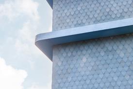
The planners wanted masonry cladding, which presented the team with a difficulty as this is not exactly lightweight. Brick slips were used to keep the weight down and fixed to an ultra high-strength precast panel which is just 75mm thick, about half that of a standard panel.
The team also wanted a unitised solution, the standard approach for office buildings, as this is much quicker and easier to install, but combining precast panels with the glass and aluminium panels of a unitised system is unusual, if not unprecedented. The glass and aluminium panels are made by Turkish cladding specialist Metalyapi, with the precast brick panels made by another Turkish company, Fibrobeton, in a different factory.
The two elements were brought to site from their respective factories as this was logistically simpler than combing these in Turkey and reduced the risk of damage if the panels were transported as one unit. The two elements were put together on the floors close to where the panels were installed.
Unusually, two new cores are right on the perimeter of the north side of the tower rather than being set in from the edge. Unitised cladding is usually installed from inside the building ﻗ the panels are launched from the edge of the floor slab on a launch pad and lifted vertically from above before being manoeuvred into position. ﻗEssentially there was no access from the edge, which made installing the cladding quite challenging,ﻗ Bee says.
The solution was to launch the panels from the slab edge adjacent to the cores and move these around the core on a monorail system. The installers worked from a cradle in front of the panels, allowing them to fix it to brackets on the core. With the structure and cladding out of the way, the rest of the job was ﻗa piece of cakeﻗ, according to Bee.
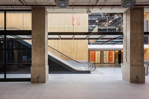
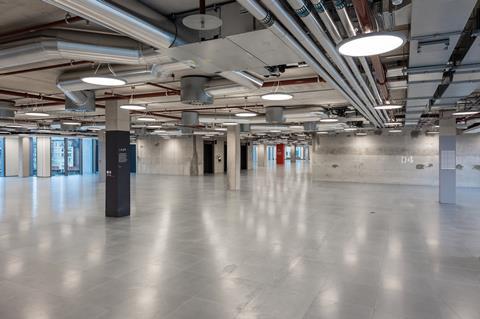
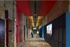
The project has saved over a third of the embodied carbon of a new-build job and created a modern, attractive workplace with all the trappings that come with that ﻗ including high-speed lifts, terraces and efficient services. And the old structure has been left proudly on display to remind everyone of the buildingﻗs origins and inject some character into the new interiors. Which is a win-win situation for those using the building, and for the planet too.
Project team
Client CIT
Architect HCL
Structural engineer AKTII
MEP engineer RHB Partnership
Cost consultant Arcadis
Facade consultant WSP
Main contractor Mace
Concrete specialist J Coffey
Steelwork specialist Bourne Steel
Interior design Stiff + Trevillion

No comments yet