The race is on to design the best 3D printing system for construction. Thomas Lane reports on how the technology is evolving, who is testing robots and why printed components can be better
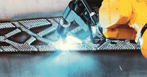
Automated construction has lots of promise: better quality, faster delivery and lower cost. But realising this potential is very slow. While many modern factories are full of robots, with barely a human to be seen, most offsite construction facilities are essentially site-based processes in a shed.
3D printing, which creates a three-dimensional object from a CAD model, is one automated process that has much to offer construction. Its flexibility fits well with the bespoke nature of construction and the industry has dabbled with the technology for producing one-off components ã and even whole buildings ã but the technology is still some way from wholesale adoption.
More about proof of concept than production
Change is coming, however. 3D printers for producing models have gone from an expensive rarity to an off-the-shelf product, with many architectural practices taking advantage of the speed, accuracy and low cost offered by 3D-printed models. Producing structural components is much more challenging due to their larger scale and the high temperatures needed to melt steel, so progress so far has been more about proof of concept than production.
In 2015, Arup pioneered the 3D printing of metal structural nodes said to be 75% lighter than traditionally produced versions. In 2018, Dutch technology start-up MX3D completed the 3D printing of a 12.5m-long stainless steel bridge, which will span a canal in the centre of Amsterdam. Although impressive, this was very much an experimental one-off.
However, an EU-funded research project is taking 3D-printed components a step closer to commercial reality. The three main partners involved in the initiative hope to use the technology for commercial production. BAE Systems wants to produce titanium and aluminium aerospace components, wind turbine manufacturer Vestas seeks to create complex turbine nacelles and Foster + Partners would like steel structural construction components. Seven additional partners are involved in the project and hope to derive commercial benefit including Autodesk, which was involved in the Amsterdam bridge project.
Multipurpose machine
The LASIMM project (this stands for ãlarge additive subtractive integrated modular machineã) is working on 3D printing technology with the ability to print three different types of metal then machine the componentsã smooth precision tolerances in one machine. Previously, 3D printed components had to be moved to other machines for non-destructive testing and finishing. It is also capable of making components up to 3m by 6m.
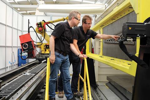
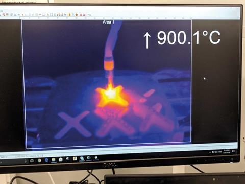
The 3D printing works on a well-established principle known as wire + arc additive manufacturing (WAAM), which was developed by Cranfield University, one of the partners on the project. It is based on MIG welding, where an electrically charged metal wire is fed through a welding torch. When the wire comes into contact with the object being welded, which is part of the electric circuit, an arc is formed that melts the wire, forming the weld.
In the case of LASIMM, the welding torch is controlled by a multi-axis robotic arm similar to those used in car manufacturing. ãItãs relatively simple ã a welding torch on the end of a robot arm that moves around depositing weld,ã explains Sam Wilkinson, associate and design system analyst at Foster + Partners. ãThe complex part is controlling that; a lot of process optimisation needs to be done to build up a shape accurately.ã
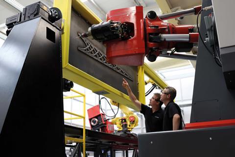
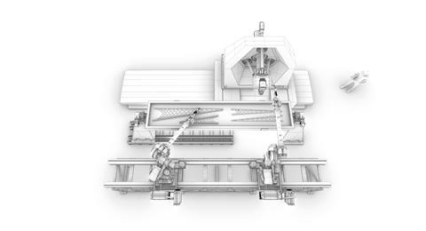
With LASIMM, the robot traces the shape of the component being made onto a metal baseplate, building it up in layers. Uniquely, it uses two welding robots to speed up the process, whereas Arupãs Amsterdam bridge project used one. Johnny van der Zwaag, project manager, research and innovation projects at Autodesk, who developed the software controlling the machine, says this was one of the most difficult parts of the project.
You need to balance the heat distortion as there is a tendency for the baseplate to warp
Sam Wilkinson
ãGetting the two robots to work in parallel was one of the major challenges, as you donãt want collisions or the welding to coincide. The question was how to divide up the job between the two, which have to operate in parallel yet independently of each other.ã
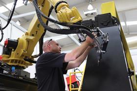
He says the robots perform periodic ãhandshakesã to let each other know which zones they are working in.
Another challenge was controlling baseplate distortion. ãAs you add material, the heat starts building up, so you need to balance the heat distortion as there is a tendency for the baseplate to warp,ã Wilkinson explains.
This is managed by the simple expedient of flipping the baseplate over once a layer has been completed and welding the same shape on the reverse side. That balances out the heat stresses and enables the component to be built up in two planes with the baseplate sandwiched in the middle.
Once the welding process is completed, the milling machine springs into action. This machines the rough welds smooth to the desired tolerances. It can also cut holes in the baseplate if the shape of the component calls for it.
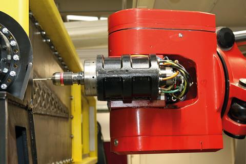
Integrating the milling process into one machine has another key advantage over doing this separately. If a defect such as a bubble is detected in a layer, the milling machine can immediately scrub this out so that it can be rewelded. Defect detection can be carried out using X-rays or electromagnetic fields.
Precision and flexibility
Fosters wanted to take advantage of the precision and flexibility of the process to create a large, complex component using the minimal amount of material. It opted to recreate one of the wooden lattice cantilever beams used on its Manchester Maggieãs Centre for cancer in steel. A key architectural element on this project was that the beams taper to a point.
The objective was to develop a structurally optimised, 5m-long cantilevered beam that could support a 500kg load at the narrow end. The structures team started from first principles and modelled how stresses pass between the upper and lower flanges of the beam, which are in tension and compression, respectively.
The machine took 120 hours to make the beam
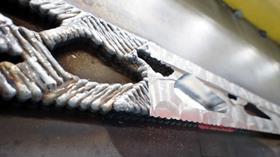
Armed with the most efficient way of managing these stresses within the beam, the team then factored in constraints including the minimum radius the milling bit could cut, manufacturing time and, crucially, the aesthetics of the finished component.
The final design features a web made of curved elements linking the upper and lower flanges. These closely follow the stress patterns within the beam, which means a minimal amount of material is needed to handle the loads.
The 3D model was then sliced into layers, ready to be manufactured. The machine took 120 hours to make the beam, which compares with around a month of production time.
Wilkinson says this is commercially viable. ãThe comparison would be with a cast component.ã
Casting involves making a physical 3D part from the model, which is then used to make the mould, which can only be used once, a process that would also take a month.
Irene Gallou, head of the specialist modelling group at Fosters, says the technology would be perfect for projects that featured components that are slightly different to usual. She cites the example of the timber gridshell roof of Crossrail Place at Canary Wharf, London.
ãCrossrail Place had a [large number] of different parts,ã she explains. ãFive hundred nodes were used for the roof and 350 of these were different and all produced manually. This would be a potential part that would be very useful if you could 3D print it.ã
Gallou says the ends of the radial roof beams used at Appleãs headquarters in California would also be a candidate for 3D printing. The beams cantilever beyond the facade and incorporate the mechanisms needed to operate the solar shading elements of the scheme.
ãThese were very complex and an ideal candidate for 3D printing,ã says Gallou. She adds that 3D printing has another key benefit ã reducing material use as components can be structurally very efficient, up to 50% lighter ã or more, as in the case of the Arup nodes.
This has a knock-on benefit which, for a roof, means the other elements can be lighter as there is less weight to support. Both Wilkinson and Gallou agree that the next test for the technology should be structural nodes.
Wilkinson says the project is almost ready for commercial production. He says two firms have invested in the technology and the practice is now waiting for the right project to work on with them. There are a few hurdles to overcome, including getting the components certified, which could be problematic if multiple parts are slightly different and need to be individually signed off. He thinks the answer is certifying the parts digitally by simulating their performance, which is how whole buildings are signed off by building control.
The process is limited by the fact the machine is designed to work horizontally
Wilkinson points out that the process is also going to be used to produce aerospace components, which are subject to a very onerous regulatory regime.
Long term, the process could be optimised further. One refinement could be building the component vertically up from one baseplate without needing to flip it over. This would have the benefit of requiring a much smaller baseplate with consequentially less waste. Fosters tried this approach, but the process is limited by the fact the machine is designed to work horizontally.
But for now, the current iteration of LASIMM is a major step towards a more automated construction future ã which is not before time.









No comments yet